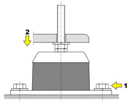
To optimize the selection of a vibration isolator one should consider:
- device’s full mass
- amount of points of support
- load concentration on a point of support
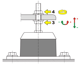
- rotational speed of spinning/rotating elements
- possible deflection
T type bushing vibration isolators selection and construction data tables.
 |
| Type and size of a vibration isolator | Axile load range
[kg] |
Maximum deflection | Dimensions [mm] | Mass 1 pc. [kg] | |||||
|---|---|---|---|---|---|---|---|---|---|
| A | B | D | d | A | h* | MxL | |||
| T – 4 | 5-70 | 15-120 | 3 | 80 | 9 | 64 | 45 | M12x50 | 0,3 |
| T – 8 | 100-250 | 200-480 | 6 | 140 | 11 | 115 | 69 | M16x85 | 1,2 |
| T – 8 – W | 450-1000 | 6 | |||||||
©All rights reserved.
* without load
** possibility of manufacturing a screw with a different thread M and length L.
** possibility of manufacturing a screw with a different thread M and length L.
Vibration isolator’s marking:
T – type
XX – vibration isolator’s size (4-8)
Y – load range (A, B or W)
Exemplary order:
Bushing vibration isolator T-XX-Y
Bushing vibration isolator T-4- A pcs.
Bushing vibration isolator T-8- W pcs.