To optimize the selection of a vibration isolator one should consider:
- device’s full mass
- amount of points of support
- load concentration on a point of support
- rotational speed of spinning/rotating elements
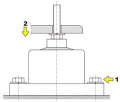
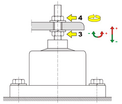
- possible deflection
K type chamber vibration isolators selection and construction data tables.
 |
| Type and size of a vibration isolator | Axile load range
[kg] |
Maximum deflection
[mm]** |
Dimensions [mm] | Mass 1 pc. [kg] | ||||||||
|---|---|---|---|---|---|---|---|---|---|---|---|---|
| A | B | D | D1 | D2 | A | g | d | h* | MxL | |||
| K – 4 | 20-80 | 60-120 | 5 | 116 | 72 | 20 | 94 | 17 | 11 | 72 | M12x50 | 1,7 |
| K – 8 | 80-350 | 150-520 | 15 | 196 | 126 | 44 | 161 | 28 | 17 | 125 | M16x75 | 8,0 |
| K – 8 – W | 500-1000 | 12 | 8,4 | |||||||||
©All rights reserved.
* without load
** possibility of manufacturing a screw with a different thread M and length L.
** possibility of manufacturing a screw with a different thread M and length L.
Vibration isolator’s marking:
K – type
XX – vibration isolator’s size (4-8)
Y – load range (A, B or W)
Exemplary order:
Chamber vibration isolator K-XX-Y
Chamber vibration isolator K-4- A pcs.
Chamber vibration isolator K-8- W pcs.