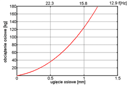
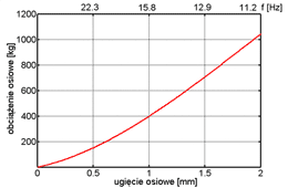
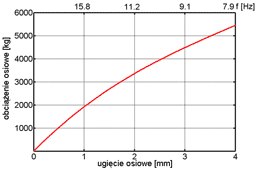
To optimize the selection of a vibration isolator one should consider:
- device’s full mass
- amount of points of support
- load concentration on a point of support
- fixing method to a mounted device
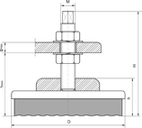
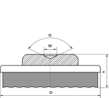
B type plate vibration isolators selection and construction data tables.
| Type and size | Axial load range[kg] | Dimensions [mm] | Mass 1 pc. [kg] | ||||||||
|---|---|---|---|---|---|---|---|---|---|---|---|
| D | H* | h* | M** | screw 1 | screw 2A screw 2B | socket | |||||
| h*min | gmax | h*min | gmax | h* | |||||||
| B – 4 | 20 – 100 | 50 | 90 | 26 | M10 | 48 | 42 | 37 | 30 | 26 | 0,2 |
| B – 8 | 100 – 200 | 90 | 115 | 36 | M12 | 64 | 50 | 50 | 37 | 36 | 0,6 |
| B – 12 | 200 – 800 | 130 | 139 | 39 | M16 | 75 | 63 | 56 | 47 | 39 | 1,5 |
| B – 16 | 800 – 1200 | 170 | 167 | 47 | M20 | 88 | 77 | 70 | 57 | 47 | 3,0 |
| B – 20 | 1200 – 2000 | 210 | 192 | 52 | M24 | 101 | 90 | 78 | 67 | 52 | 5,2 |
| B – 24 | 2000 – 5000 | 250 | 198 | 53 | M24 M30 |
96 88 |
90 81 |
79 85 |
67 52 |
53 | 6,2 6,5 |
** possibility of manufacturing a screw with a different thread M and length L.
Screw 1 and Screw 2A inserted into the bushing of a vibration isolator, screw 2B screwed into the bushing of a vibration isolator. Leveling of a device on a vibration isolator’s fixing screw.
Plate vibration isolator B-XX-Y
B – type
XX – vibration isolator’s size (4-24)
Y- fixing type (screw 1, screw 2A, screw 2B or socket)
Exemplary order:
Plate vibration isolator B-4 pcs. – screw 1 pc.
Plate vibration isolator B-12 pcs. – screw 2B pcs.
Plate vibration isolator B-16 socket pcs.


